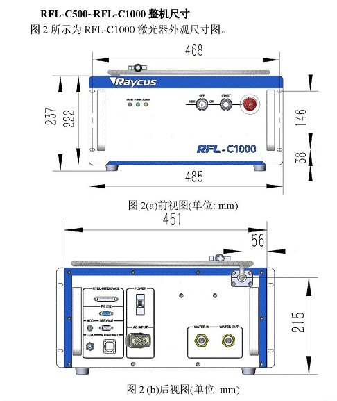
锐科C系与控制盒的控制接线(中英)注意: 1.请确保文中的激光器图示与您使用的激光器为同一型号 2.如激光器厂家信号更改,则下列接线失效,请按照厂家提供的定义接线 Attention: 1. Please ensure that the laser icon in the article is the same model as the laser you are using 2. If the laser manufacturer's signal changes, the following wiring fails. Please connect the wiring according to the manufacturer's definition 锐科小体积RFL-C系图示 Illustration of the small volume RFL-C series of Rayco
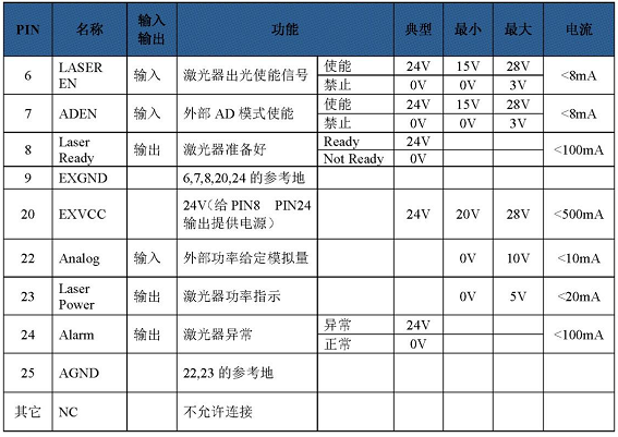
激光器信号接口CTRL-INTERFACE定义(DB25) Laser Signal Interface CTRL-INTERFACE Definition (DB25)
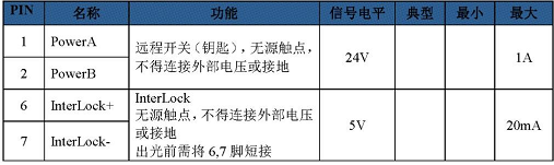
激光器信号接口SERVRCE定义(DB9) Laser Signal Interface SERVRCE Definition (DB9)
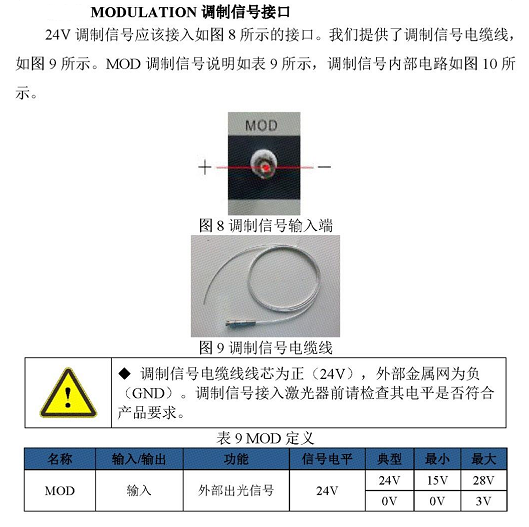
根据以上定义,接线方式: 1.首先短接激光器信号接口SERVRCE定义(DB9)的6和7 2.MODULATION插口的电缆线线芯(MOD+调制信号)接控制盒的信号接口三的7号脚 3.MODULATION插口的外部金属网(MOD-调制信号)接控制盒的信号接口三的6号脚 4.DB25的22脚(外部模拟量给定0-10V+)接控制盒的信号接口三的5号脚 5.DB25的25脚(22.23的参考地)接控制盒的信号接口三的4号脚 6.DB25的6脚(激光使能)接控制盒的信号接口三的2号脚 7.DB25的9脚(6.7.8.20.24的返回端)接控制盒的信号接口三的4号脚 8.DB25的7脚(外部AD模式)接控制盒的信号接口三的3号脚 9.DB25的20号脚(PIN8.PIN24的电源)接控制盒的信号接口三的3号脚 According to the above definition, the wiring mode: 1. First short-circuit 6 and 7 of the laser signal interface SERVRCE definition (DB9) 2.MODULATION jack of the cable wire core (MOD+ modulation signal) is connected to pin 7 of signal interface 3 of the control box 3. The external metal mesh (MOd-modulated signal) of the MODULATION jack is connected to pin 6 of signal interface 3 of the control box 4. Connect pin 22 of DB25 (external analog 0-10V+) to pin 5 of signal interface 3 of the control box 5. Connect pin 25 of the DB25 (reference ground of 22.23) to pin 4 of signal port 3 of the control box 6. Connect pin 6 (laser enabled) of the DB25 to pin 2 of signal port 3 of the control box 7. Connect pin 9 of the DB25 (return end of 6.7.8.20.24) to pin 4 of signal port 3 of the control box 8. Connect pin 7 of the DB25 (in external AD mode) to pin 3 of signal port 3 on the control box 9. Connect pin 20 of the DB25 (power supply of PIN8.PIN24) to pin 3 of signal port 3 of the control box |