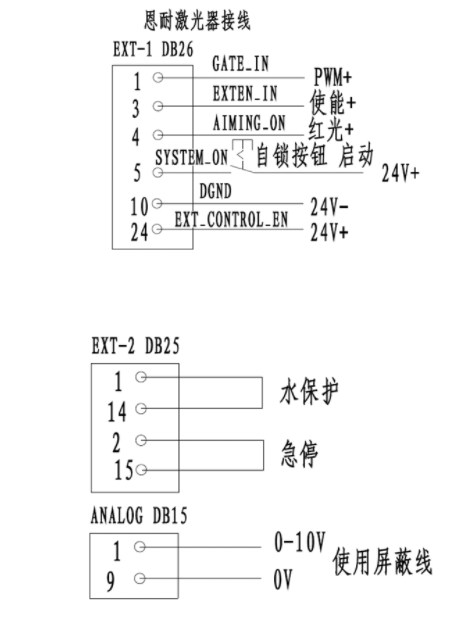
nLight恩耐激光器与控制盒的控制(中英)使用外部接口控制激光的步骤示例: 1.确保EXT-2安全连接器中的互锁销已关闭 2.将EXTEN_IN,CLR_ERR和SYSTEM_ON设置为低电平。 3.使用交流电源断路器为激光器施加交流电源。 4.将SYSTEM_ON设置为高以提供上升沿。 5.等待至少5秒钟,然后确认ERR输出为低电平且RDY输出为高电平。 6.将EXTEN_IN设置为高电平以提供上升沿。 7.等待2秒钟,确认RDY输出为高电平且EMISS输出为高电平。 8.激光现在将遵循GATE_IN和ANALOG_IN来控制激光发射和功率。 9.监控ERR输出。如果ERR变高,激光器就会关闭。请参见下图以使用硬件清除ERR信号。 10.将EXTEN_IN设置为低电平以关闭激光二极管驱动器。 11.将SYSTEM_ON设置为低以将激光器移出STANDBY状态或打开互锁连接以移动激光器处于关闭状态并切断激光二极管驱动器的电源 Example of steps to control a laser using an external interface: 1. Make sure the interlock pin in the EXT-2 safety connector is closed 2. Set the EXTEN_IN, CLR_ERR and SYSTEM_ON to low. 3. Use an AC power circuit breaker to apply AC power to the laser. 4. Set SYSTEM_ON to high to provide rising edges. 5. Wait at least 5 seconds, then confirm that the ERR output is low and the RDY output is high. 6. Set the EXTEN_IN high to provide rising edge. 7. Wait 2 seconds to confirm that the RDY output is high and the EMISS output is high. 8. The laser will now follow the GATE_IN and ANALOG_IN to control laser emission and power. 9. Monitor ERR output. If the ERR becomes high, the laser shuts down. See the figure below to clear the ERR signal using hardware. 10. Set the EXTEN_IN low to turn off the laser diode driver. 11. Set the SYSTEM_ON to low to move the laser out of the STANDBY state or open the interlock connection to move the laser in the off state and cut off the power to the laser diode driver
必须使用HW模式 外部24脚高电平信号启用HW模式,如果激光是在'HW'模式下,24脚信号的下降沿将禁用所有输入并将激光转换为“关闭”状态。24脚也可以不用接线 ,HW模式可以用软件修改 启动顺许: 模式使用“HW”,钥匙打到on, 给5脚启动信号(实现:5脚接控制盒3脚,中间装一个带锁的按钮) 5s后给使能(实现:3脚接控制盒的3脚,中间装一个带锁的按钮) 再有P+信号出光 HW mode must be used The external 24-pin high signal enables HW mode, and if the laser is in 'HW' mode, the falling edge of the 24-pin signal will disable all inputs and transition the laser to the "off" state. The 24-pin can also be modified without wiring, and the HW mode can be modified with software Startup Order: The mode uses "HW", the key hits on, Start signal for 5 pins (realization: 5 pins connected to 3 pins of the control box, a button with lock in the middle) Enable after 5s (realization: 3 pins connected to the 3 pins of the control box, a button with a lock in the middle) Then there is the P+ signal coming out |