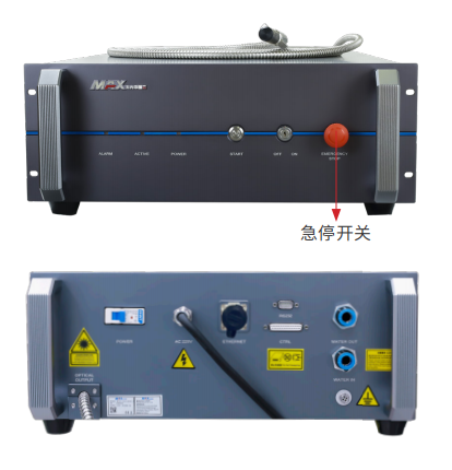
创鑫激光器与控制盒的控制接线(中英)注意: 1.请确保文中的激光器图示与您使用的激光器为同一型号 2.如激光器厂家信号更改,则下列接线失效,请按照厂家提供的定义接线 Attention: 1. Please ensure that the laser icon in the article is the same model as the laser you are using 2. If the laser manufacturer's signal changes, the following wiring fails. Please connect the wiring according to the manufacturer's definition ① 创鑫MFSC -1000X/1500X图示 ① Illustration of Chuangxin MFSC-1000X /1500X
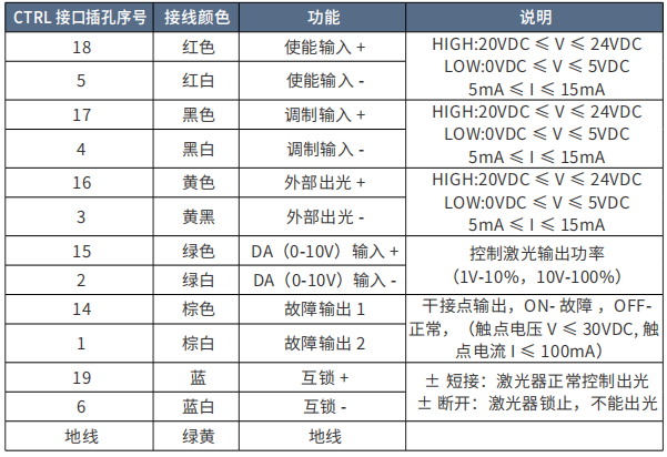
CTRL 接口定义表
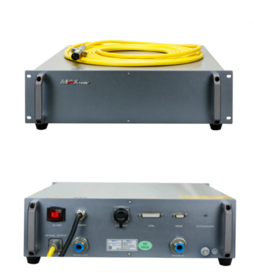
创鑫MFSC 系列(1000X-1500X) 根据以上定义,接线方式(创鑫引脚有线标,可按照线标接线): 短接19脚和6脚 1.DB24的17号脚(MOD+调制信号)接控制盒的信号接口三的7号脚 2.DB24的4号脚(MOD-调制信号)接控制盒的信号接口三的6号脚 3.DB24的15脚(模拟量+)接控制盒的信号接口三的5号脚 4.DB24的2脚(参考地)接控制盒的信号接口三的4号脚 5.DB24的18脚(使能+)接控制盒的信号接口三的2号脚 6.DB24的5脚(使能-)接控制盒的信号接口三的4号脚 钥匙拧到ON,开机后等待自检完成按下START即可 Chuangxin MFSC Series (1000X-1500X) According to the above definition, the wiring method (Chuangxin pin wired mark, can be connected according to the line mark) : Short connect pin 19 and pin 6 1. Connect pin 17 (MOD+ modulated signal) of DB24 to pin 7 of signal interface 3 of the control box 2. Connect pin 4 (MOD-modulated signal) of DB24 to pin 6 of signal interface 3 of the control box 3. Connect pin 15 (analog +) of the DB24 to pin 5 of signal interface 3 of the control box 4. Connect pin 2 (reference ground) of the DB24 to pin 4 of signal port 3 of the control box 5. Connect pin 18 (Enable +) of the DB24 to pin 2 of signal port 3 on the control box 6. Connect pin 5 (Enable -) of the DB24 to pin 4 of signal port 3 of the control box Turn the key ON, START the machine, wait for the completion of the self-test, and press Start ② 创鑫MFSC -1000X/1500X(G5.0)图示 ② Chuangxin MFSC-1000X /1500X (G5.0) icon
CTRL 接口定义表
创鑫MFSC -1000X/1500X(G5.0) 根据以上定义,接线方式(创鑫引脚有线标,可按照线标接线): 短接19脚和6脚 1.DB24的17号脚(MOD+调制信号)接控制盒的信号接口三的7号脚 2.DB24的4号脚(MOD-调制信号)接控制盒的信号接口三的6号脚 3.DB24的15脚(模拟量+)接控制盒的信号接口三的5号脚 4.DB24的2脚(参考地)接控制盒的信号接口三的4号脚 5.DB24的18脚(使能+)/16脚一起接控制盒的信号接口三的2号脚 6.DB24的5脚(使能-)/3脚一起接控制盒的信号接口三的4号脚 激光器通电后,扣动扳机后使能信号触发外部出光即可 Chuangxin MFSC-1000X /1500X (G5.0) According to the above definition, the wiring method (Chuangxin pin wired mark, can be connected according to the line mark) : Short connect pin 19 and pin 6 1. Connect pin 17 (MOD+ modulated signal) of DB24 to pin 7 of signal interface 3 of the control box 2. Connect pin 4 (MOD-modulated signal) of DB24 to pin 6 of signal interface 3 of the control box 3. Connect pin 15 (analog +) of the DB24 to pin 5 of signal interface 3 of the control box 4. Connect pin 2 (reference ground) of the DB24 to pin 4 of signal port 3 of the control box 5. Connect pin 18 (Enable +)/Pin 16 of the DB24 to pin 2 of signal port 3 on the control box 6. Pin 5 (Enable -) and pin 3 of the DB24 connect to pin 4 of signal port 3 on the control box After the laser is powered on, the trigger is pulled to enable the signal to trigger the external light |