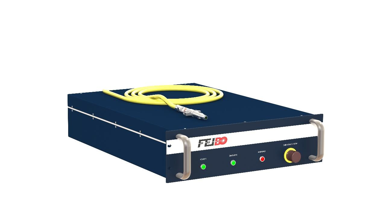
飞博激光器与控制盒的控制接线(中英)注意: 1.请确保文中的激光器图示与您使用的激光器为同一型号 本文适用 YDFL-1000-CW 光纤激光器 2.如激光器厂家信号更改,则下列接线失效,请按照厂家提供的定义接线 Attention: 1. Please ensure that the laser diagram in the article is the same model as the laser you use. This article applies to YDFL-1000-CW fiber laser 2. If the laser manufacturer's signal changes, the following wiring fails. Please connect the wiring according to the manufacturer's definition YDFL-1000-CW 光纤激光器图示 Illustration of the YDFL-1000-CW fiber laser
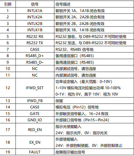
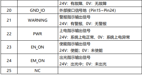
外部控制信号接口(DB25)
根据以上定义,接线方式: 首先短接激光器DB25的1和4,2和3 (PWM信号) DB25的15脚(外部触发信号GATE)接控制盒的信号接口三的7号脚 DB25的16脚(GND_IO)接控制盒的信号接口三的6号脚 (模拟量给定) DB25的12脚(IFWD_SET外部模拟量给定0-10V+)接控制盒的信号接口三的5号脚 DB25的14脚(CAST/返回端)接控制盒的信号接口三的4号脚 (使能信号) DB25的18脚(EX_EN激光使能)接控制盒的信号接口三的2号脚 DB25的20脚(15-24的返回端)接控制盒的信号接口三的4号脚 (红光触发) DB25的17脚(红光)接控制盒的信号接口三的3号脚 According to the above definition, the wiring mode: First short-circuit the 1 and 4,2 and 3 of the laser DB25 (PWM signal) Pin 15 (external trigger signal GATE) of the DB25 is connected to pin 7 of signal port 3 of the control box Connect pin 16 (GND_IO) of the DB25 to pin 6 of signal port 3 of the control box (Analog quantity given) Pin 12 of the DB25 (IFWD_SET external analog 0-10V+) is connected to pin 5 of signal interface 3 of the control box Pin 14 (CAST/ return end) of the DB25 is connected to pin 4 of signal interface 3 of the control box (Enable signal) Connect pin 18 of the DB25 (EX_EN laser enabled) to pin 2 of signal port 3 of the control box Pin 20 of the DB25 (return end of 15-24) is connected to pin 4 of signal interface 3 of the control box (red light trigger) Pin 17 (red light) of the DB25 is connected to pin 3 of signal interface 3 of the control box |