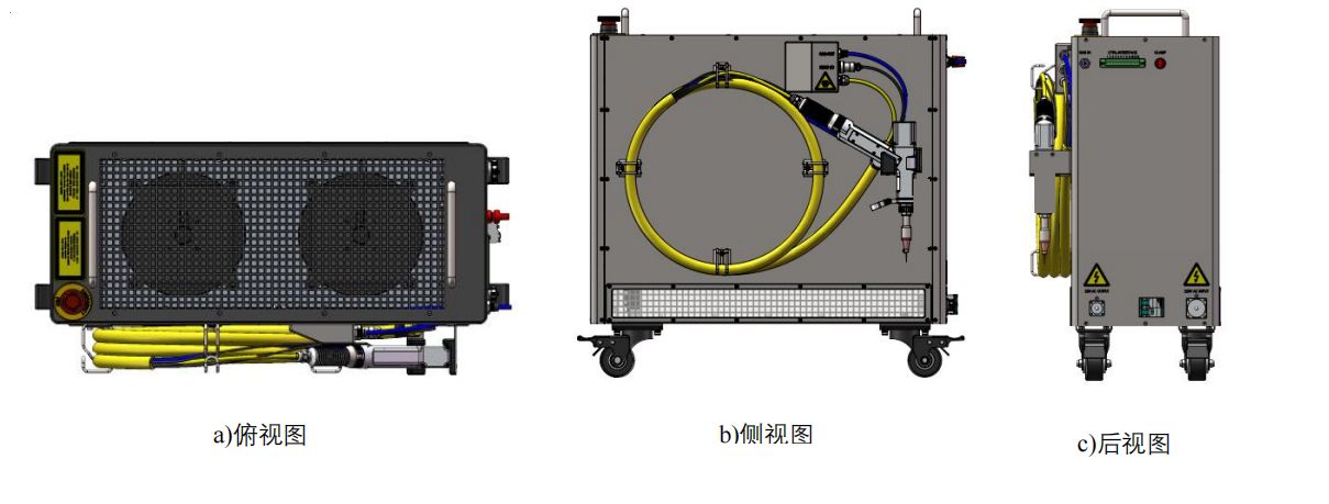
热刺FCA风冷系列激光器与焊接枪的控制接线(中英)注意: 1.请确保文中的激光器图示与您使用的激光器为同一型号 本文适用 FCA1000/FCA1500型号 2.如激光器厂家信号更改,则下列接线失效,请按照厂家提供的定义接线 Attention: 1. Please ensure that the laser icon in the article is the same model as the laser you are using. This article applies to FCA1000/FCA1500 model 2. If the laser manufacturer's signal changes, the following wiring fails. Please connect the wiring according to the manufacturer's definition FCA1000/FCA1500机型图示 FCA1000/FCA1500 model icon
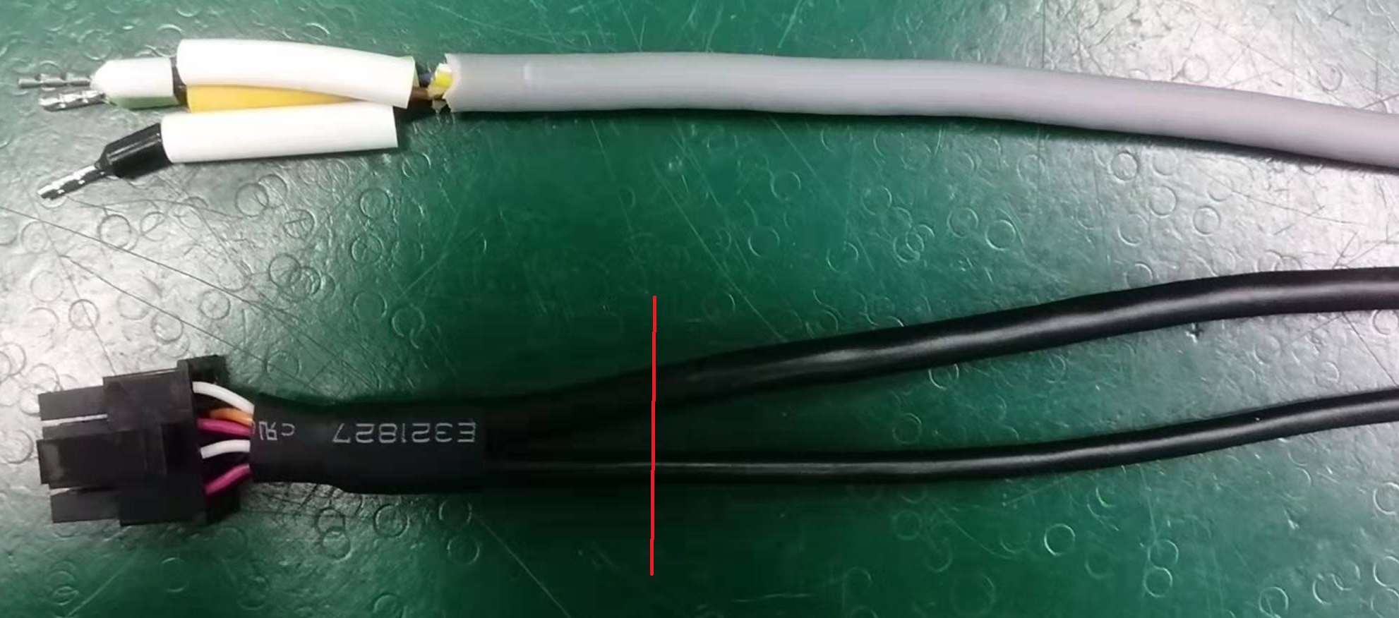
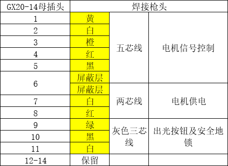
1.安装前准备 1.1 热刺标准风冷整机 1.2 超强焊接枪头 1.3 超强焊接驱动模块 (务必为模拟版,请在下单前询问) 1.4 导热硅脂 1.5 拆解专用内六角及驱动固定螺丝 1.6 GX20-14母插头(热刺附件) 1. Prepare for installation 1.1 Spurs standard air cooling machine 1.2 Super strong welded gun head 1.3 Super welding drive module (Be sure to be a simulation version, please ask before placing an order) 1.4 Thermal grease 1.5 Remove the special hex socket and drive fixing screws 1.6GX20-14 Female Plug (Tottenham accessories) 2.接线方法 2.1控制部分接线 2.1.1驱动模块的连线安装 通过拆开激光器的后面板,于设备的左下找到驱动安装的位置,对应接线安装驱动部分,如视频 2. Wiring methods 2.1 Connecting Cables to the control part 2.1.1 Cable Installation of the Driver Module By disassembling the rear panel of the laser, find the driver installation position on the lower left side of the device, corresponding to the wiring and installation of the driver part, such as video 2.2.1 焊接枪的连线安装 焊接枪共有3根线,其中两根黑色的为电机控制线,一根灰色的为扳机按钮及安全地锁线, 剪断后均连接到GX20-14母插头上,最后插到激光器侧盖板的HEAD I/O上 2.2.1 Connecting the welding gun The welding gun has a total of 3 wires, of which two are black for the motor control wire, and one is gray for the trigger button and safety lock wire. After cutting, they are connected to the GX20-14 female plug, and finally inserted into the HEAD I/O of the laser side cover plate
引脚定义如下 Pins are defined as follows
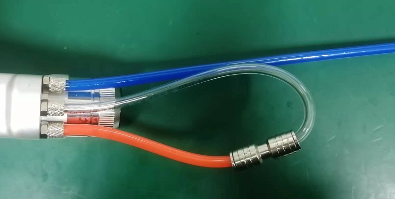
2.2气路部分 超强焊接枪为水冷风冷通用型号,因此会有三根管道,使原水路循环,如下图绿色管道连接到激光器侧盖板的GAS OUT 气管上即可,请注意,GAS IN输入的焊接气体压力不可大于1MPa 2.2 Gas path part The super welding gun is a water-cooled and air-cooled universal model, so there are three pipes to circulate the original water. The green pipe IN the following figure can be connected to the GAS OUT GAS pipe of the laser side cover plate. Please note that the welding gas pressure input by the GAS IN the gas can not be greater than 1MPa
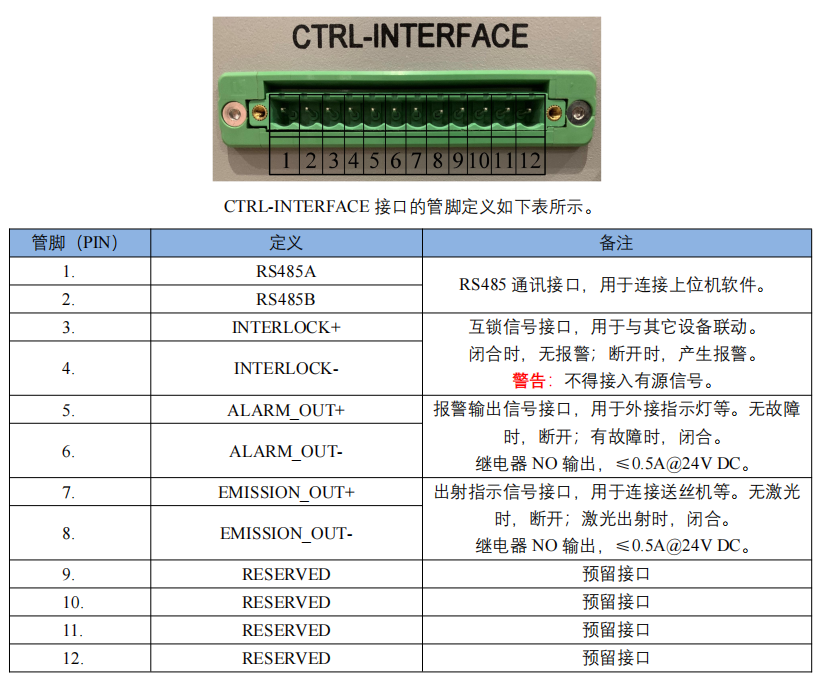
2.3 激光器部分接线 2.3.1 安全地锁接激光器尾部的CLAMP上,与加工工件相连,提供安全地锁保护 2.3.2 激光器尾部的CTRL-INTERFACE为12 芯控制信号接口,具体引脚定义如下,提供送丝信号及通讯功能 2.3 Cable Connections to the laser 2.3.1 Securely lock CLAMP on the laser tail and connect to the workpiece to provide safe lock protection 2.3.2 The CTRL-INTERFACE at the tail of the laser is a 12-core control signal interface. The specific pins are defined as follows to provide wire feed signals and communication functions
3.激光器使用方法 参照热刺说明书 3. Laser use method Refer to the Spurs instructions |